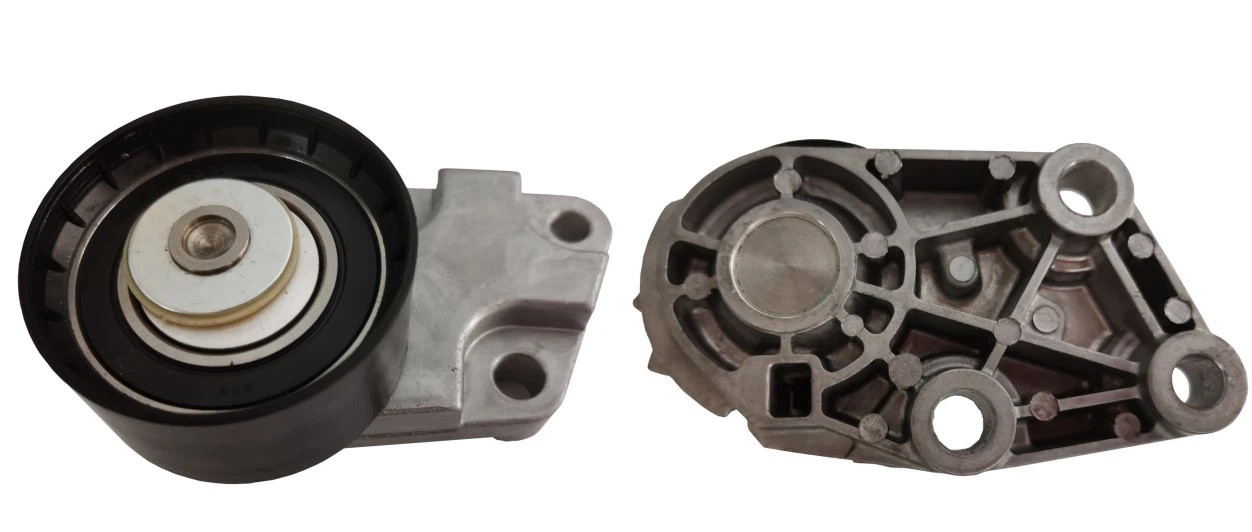
Recommeded Installation Procedure For 96350550
Date: 2024-08-20 Click: 241
Timing Tensioner (96350550) --- GM/DAEWOO 1.5/1.6L DOHC
Initial Preparation:
Caution: The procedure to access the timing belt tensioner and all other timing driven components must be done according to the car manufacturer's guidelines.
Engine temperature:
1. The tensioner must be installed on the engine at room temperature by allowing the engine to stabilize to room temperature for proper belt tension adjustment. Do not attempt to install a tensioner onto a hot engine. (For reference, the minimum engine cooling period is 4 hours in tropical climatic regions).
Crankshaft and Camshaft TDC position setup:
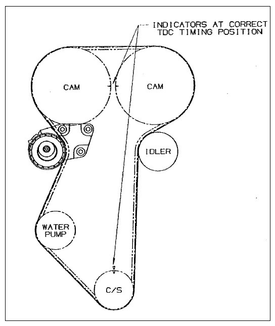
2. Rotate the crankshaft CLOCKWISE ONLY to TDC (Top Dead Center) position (i.e. #1 cylinder firing position), follow car manufacturer's guidelines. For reference only see below picture.
Removal of the Timing Belt
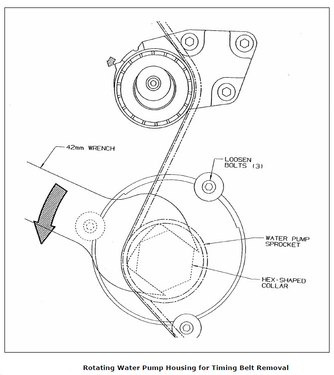
3. Loosen the three (3) Water Pump Clamping Bolts just slightly so that the Water Pump Housing can be rotated (Picture below).
Warning: Engine coolant may leak during this process.
4.Rotate the Water Pump Housing COUNTERCLOCKWISE with a 42mm Wrench (Figure 2). The Wrench should fit around the Hex-shaped Collar beneath the Water Pump Sprocket (Figure 3).
5. Keep rotating the Water Pump Housing until the belt becomes loose. Remove the belt and the OLDTBT. It is always recommended to replace the timing belt during the replacement of the tensioner.
Installation of the Timing Belt Tensioner
6. Install a new tensioner onto the engine and tighten the three (3) M8 Tensioner Mounting Bolts with 28.0 ± 5.5 Nm of torque.
7. Install a new timing belt being careful to engage the appropriate teeth of all the corresponding sprockets as per drive layout starting with the crankshaft and working counterclockwise. (Caution: Do not disturb the position of the crankshaft or camshaft sprockets during this
procedure.)
8. Rotate the Water Pump Housing CLOCKWISE with the 42mm Wrench. The tensioner pulley will move against the belt and the Arm Pointer indicator" will eventually start to move CLOCKWISE.
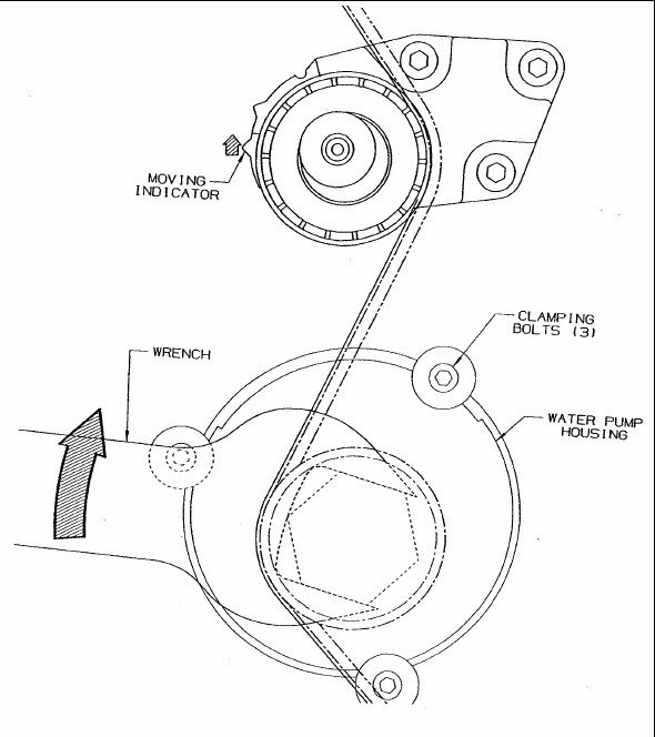
9. Continue rotating the Water Pump Housing until the Moving Indicator* aligns with the Stationary Indicator** on the tensioner bracket assembly, then tighten the three Clamping Bolts (25Nm) around the Water Pump Housing.
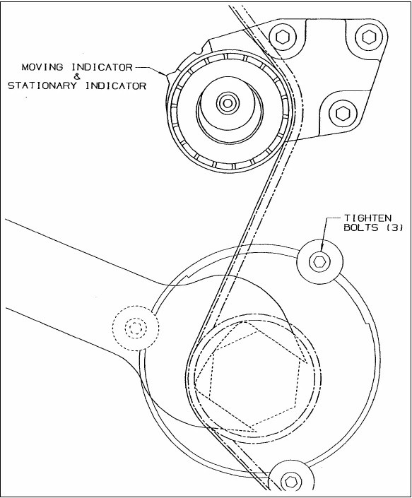
Verification of the Nominal Position
10. Remove the Wrench and any other tools used for the alignment of the TDC position, then rotate the crankshaft two (2) complete revolutions manually for proper seating of the belt until the crankshaft is repositioned at the TDC position.
Check the TDC alignment of the crankshaft and the camshaft, Figure 4. If the alignment of all the sprockets is within the guidelines, the installation is complete. If any of the crankshaft or camshaft sprockets are not aligned at the TDC position, the belt has to
be removed and the installation procedure has to be repeated starting at step 3.
Caution: if the alignment of the crankshaft and its corresponding mark on the engine is missed, rotate the Crankshaft 2 more full rotations to the alignment point.
11. Check the position of the Moving Indicator.
- If the Moving Indicator aligns with the Stationary Indicator, the installation is complete
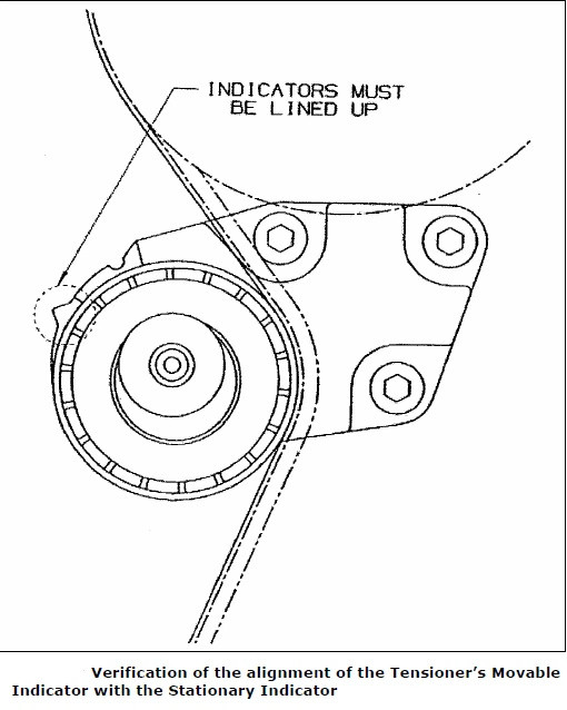
- If not, go to step #12. The installation must be repeated until the proper position is achieved.
Readjustment
12. Loosen the three (3) Water Pump Clamping Bolts around the Water Pump Housing for readjustment. Rotate the Water Pump Housing in the appropriate direction to align the tensioner's Arm Moving Indicator with the Stationary Indicator on the bracket.
13. Tighten the three (3) Water Pump Clamping Bolts (25Nm) around the Water Pump Housing and re-verify the tensioner position (repeat steps #10 and #11).
